Clipping
GUI nodes can be used as clipping nodes—masks that control how other nodes are rendered. This manual explains how this feature works.
Creating a clipping node
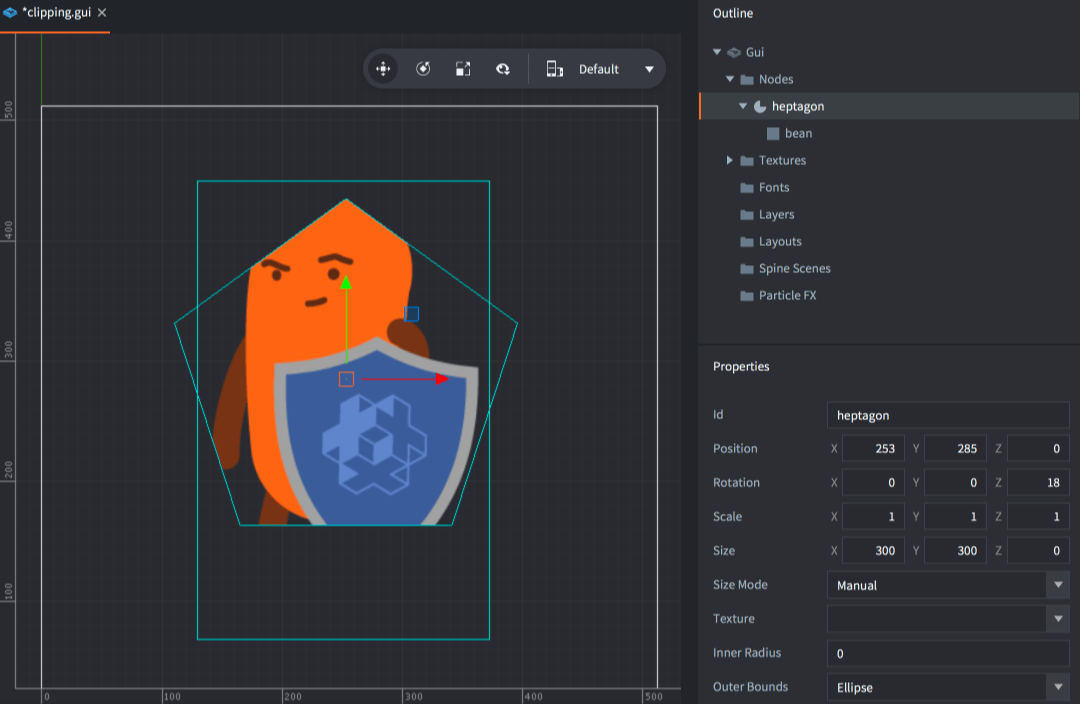
Box, Text and Pie nodes can be used for clipping. To create a clipping node, add a node in your GUI, then set its properties accordingly:
- Clipping Mode
- The mode used for clipping.
Nonerenders the node without any clipping taking place.Stencilmakes the node writing to the current stencil mask.
- Clipping Visible
- Check to render the content of the node.
- Clipping Inverted
- Check to write the inversion of the node’s shape to the mask.
Then add the node(s) you want to be clipped as children to the clipping node.

Stencil mask
Clipping works by having nodes writing to a stencil buffer. This buffer contains clipping masks: information that that tells the graphics card whether a pixel should be rendered or not.
- A node with no clipper parent but with clipping mode set to
Stencilwill write its shape (or its inverse shape) to an new clipping mask stored in the stencil buffer. - If a clipping node has a clipper parent it will instead clip the parent’s clipping mask. A clipping child node can never extend the current clipping mask, only clip it further.
- Non clipper nodes that are children to clippers will be rendered with the clipping mask created by the parent hierarchy.

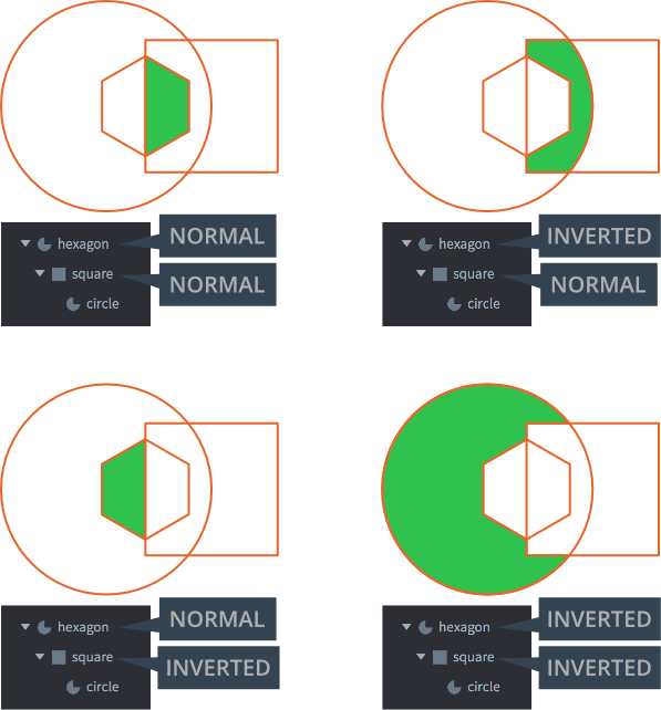
Here, three nodes are set up in a hierarchy:
- The hexagon and square shapes are both stencil clippers.
- The hexagon creates a new clipping mask, the square clips it further.
- The circle node is a regular pie node so it will be rendered with the clipping mask created by its parent clippers.
Four combinations of normal and inverted clippers are possible for this hierarchy. The green area marks the part of the circle that is rendered. The rest is masked:

Stencil limitations
- The total number of stencil clippers can not exceed 256.
- The maximum nesting depth of child stencil nodes is 8 levels deep. (Only nodes with stencil clipping count.)
- The maximum number of stencil node siblings is 127. For each level down a stencil hierarchy, the max limit is halved.
- Inverted nodes have a higher cost. There is a limit to 8 inverted clipping nodes and each will halve the max amount of non-inverted clipping nodes.
- Stencils render a stencil mask from the geometry of the node (not the texture). It is possible to invert the mask by setting the Inverted clipper property.
Layers
Layers can be used to control rendering order (and batching) of nodes. When using layers and clipping nodes the usual layering order is overridden. Layer order always take precedence over the clipping order—if layer assignments are combined with clipping nodes, clipping could happen out-of-order if a parent node with clipping enabled belongs to a higher layer than its children. The children with no layer assigned will still respect the hierarchy and subsequently be drawn and clipped after the parent.
A clipping node and its hierarchy will be drawn first if it has a layer assigned and in the regular order if no layer is assigned.

In this example, both the clipper nodes “Donut BG” and “BG” are using the same layer 1. The render order between them will be according to the same order in the hierarchy where “Donut BG” is rendered before “BG”. However, the child node “Donut Shadow” is assigned to the layer 2 which has a higher layer order and thus will be rendered after the both clipping nodes. In this case, the render order will be:
- Donut BG
- BG
- BG Frame
- Donut Shadow
Here you can see that the “Donut Shadow” object will be clipped by both clipping nodes due to the layering, eventhough it is only a child to one of them.
- English
- 中文 (Chinese)
- Español (Spanish)
- Français (French)
- Νεοελληνική γλώσσα (Greek)
- Italiano (Italian)
- Język polski (Polish)
- Português (Portuguese)
- Русский (Russian)
- Українська (Ukranian)
Did you spot an error or do you have a suggestion? Please let us know on GitHub!
GITHUB